THE CYBER INFORMANT
Projects/BuzzCane Mk.III: Switching the ATmega328-PU to an ATTiny85, Adding a Potentiometer to Control Distance Threshold, and Circuit Protection
3/30/2024
The third iteration of my project, "BuzzCane. I've switched out the big, 28-pins, ATmega328-PU for a much smaller yet capable enough, 8-pins, ATTiny85. I'll also be adding a way to give the user a way to control the threshold distance value at which to trigger the buzzer.
According to the datasheet, the ATTiny85, an 8-bit MCU based on the AVR RISC architecture. Chosen by me for it's small size and low cost. It has 8Kb for storing program code (Flash Memory), SRAM (temporary data) of 512 Bytes, EEPROM: 512 Bytes (for storing non-volatile data that persists even after power is turned off),
and has 8 pins, 1 for reset, 1 for VCC, and 1 for GND, leaving us with 5 GPIO pins. It has a clock freq. of up tp 8 MHz, not requiring an external oscillator to work. It also has several power-saving modes for battery-powered applications, as well as a watchdog timer. The length of the MCU is 9.91 mm, width is 6.99 mm,
height is around 4.95 mm including the "legs", its weight is negligible.

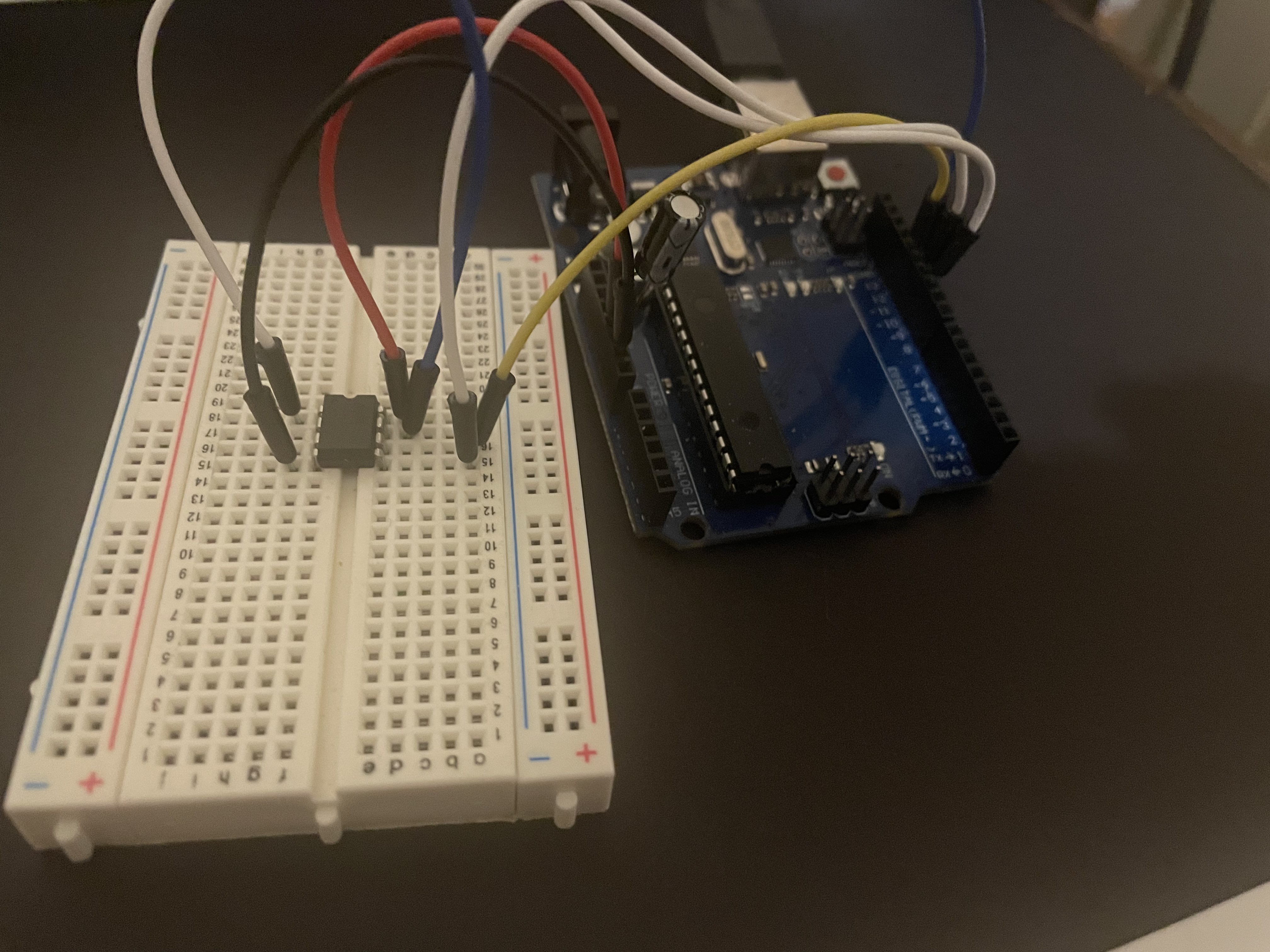
In the image above, the numbering convention of the ATTINY is different to that of the Arduino, and so physical pin 5 is pin 0, and physical pin 2 is pin 3. It did take me a few minutes after programming the MCU to figure out why it isn't working and so please keep this alternative numbering convention in mind as you work.
Using an Arduino UNO with an ATMega328 as an ISP programmer
The ATTiny85 with all of its appeal comes with a technical cost, the inconvenience of uploading a program to it. You can use a dedicated ISP programmer or you can turn a spare Arduino UNO into an ISP Programmer pretty easily.Firstly, open your Arduino IDE software, we will need to add support for the ATTiny85 as the Arduino IDE does not include it by default. Go to the "Preferences" tab, scroll down to "Additional Bord managers URLs", and copy-paste the following in the text box:
https://drazzy.com/package_drazzy.com_index.json
Now press "OK" at the bottom then restart the Arduino IDE
Then from the IDE click on Tools --> Board --> Board Manager
And type "ATTinyCore" in the search box and install that package
Now click on Tools --> Board --> ATTinyCore, and you should see ATTiny25/45/85 (No Bootloader). Don't click on it yet.
Now we will work on turning out Arduino UNO into an ISP Programmer. To do that: Click on File --> Examples --> Arduino ISP >> ArduinoISP
A new window will open, now plug-in your Arduino UNO board, make sure it's connected on the correct port on by checking Tools --> Port. Now on the ArduinoISP sketch window that opened, click on "Upload".
Now that we turned our Arduino UNO into an ISP programmer, we can use it to burn our program into our MCU.
We need to place our ATTINY on top of a breadboard and wire it to the Arduino. we will follow the wiring displayed below:

Below is my wiring:
I connected a 10 µf capacitor to the Reset female pin adapter and the cathode of it to the GND pin to prevent the device from resetting immediately.
Now we have to configure our Arduino IED to the settings we want to burn onto our ATTiny. click on Tools --> Board --> ATTinyCore, and you should see ATTiny25/45/85 (No Bootloader), back to Tools and pick Chip --> ATtiny85. Then Clock Source: 8 Mhz (internal). As the ATTiny has an internal oscillator and so we would not need any external crystal oscillator. Then finally, click on Programmer and pick "Arduino as ISP" and leave everything else as is. Below is a screenshot of my configurations:

And because most likely, the ATTiny doesn't come with a bootloader that enables it to accept Arduino code, we would have to click on "Burn Bootloader", and then we can write our code and upload it onto the Chip!
The Updated Schematic
I have replaced the ATMega328-PU for the much smaller ATTiny85, and added a potentiometer (variable resistor) to control the threshold range at which if a solid object is detected, the buzzer buzzes. I have also added a Schottky Diode (IN5817) on the positive terminal of the 9V battery before the 10uf capacitor and the voltage regulator.
The schottky diode prevents DC current from flowing the wrong way if the 9V battery's terminals are connected the wrong way. As in if the negative terminal of the battery is connected to where the positive terminal should go and vice-a-versa. The diode's operating voltage runs a maximum of 20V, a forward voltage drop of 450 mV, and a maximum current handling of 1 Ampere. The use of the appropriate schottky diode is important to prevent reverse current.
The potentiometer was added to actively adjust the threshold value at which, if a solid object is detected, a signal is sent to the active buzzer to trigger it. The potentiometer has 3 pins, 1 pin on one end is connected to VCC, other end is connected to GND, and the middle pin, also called the "wiper", is connected to analog/digital pin #3
The potentiometer adjusts the threshold value by working as a variable resistor, which sends varying voltages to Analog/Digital pin # 3, Based off of the voltage read on that pin, a corresponding threshold distance is read from a pre-determined Voltage-to-distance table (Struct in C) to determine the threshold value. And based off of that range of values, a threshold is chosen.
below is the code implementaiton of all the above logic:
#define TRIG_PIN 0 // ATmega328 pin GPIO28 connected to Ultrasonic Sensor's TRIG pin
#define ECHO_PIN 1 // ATmega328 pin GPIO27 connected to Ultrasonic Sensor's ECHO pin
#define buzzerPin 2 // ATmega328 pin GPIO14 connected to Active Buzzer's positive pin
#define potPin 3 // Analog input pin connected to potentiometer

float duration_us;
uint8_t distance_cm;
bool buzzerActive = false; // Flag to track buzzer activation

// Define reference voltage (assuming 5V for Arduino)
const float referenceVoltage = 5.0;

// Lookup table for voltage-to-threshold mapping (modify values as needed)
const struct {
    float minVoltage;
    float maxVoltage;
    uint8_t threshold_cm;
} voltageThresholds[] = {
    {0.1, 0.5, 10},
    {0.5, 1.0, 25},
    {1.0, 1.5, 50},
    {1.5, 2.0, 75},
    {2.0, 2.5, 100},
    {2.5, 3.0, 125},
    {3.0, 3.5, 150},
    {3.5, 4.0, 175},
    {4.0, 4.5, 200},
    {4.5, 5.0, 225},
};

// Number of entries in the lookup table
const int numThresholds = sizeof(voltageThresholds) / sizeof(voltageThresholds[0]);

void setup() {
    pinMode(buzzerPin, OUTPUT);
    pinMode(TRIG_PIN, OUTPUT);
    pinMode(ECHO_PIN, INPUT);
    pinMode(potPin, INPUT); // Set potentiometer pin as analog input

    delay(500);
}

void loop() {
    // Read analog value from potentiometer
    int potValue = analogRead(potPin);

    // Convert analog value to voltage (consider reference voltage)
    float inputVoltage = potValue * referenceVoltage / 1023.0;

    // Find threshold distance using lookup table
    uint8_t threshold_cm = 0;
    for (int i = 0; i < numThresholds; i++) {
        if (inputVoltage >= voltageThresholds[i].minVoltage && inputVoltage < voltageThresholds[i].maxVoltage) {
        threshold_cm = voltageThresholds[i].threshold_cm;
        break;
        }
    }

    // Generate 10-microsecond pulse to TRIG pin
    digitalWrite(TRIG_PIN, HIGH);
    delayMicroseconds(10);
    digitalWrite(TRIG_PIN, LOW);

    // Measure duration of pulse from ECHO pin
    duration_us = pulseIn(ECHO_PIN, HIGH);

    // Calculate the distance
    distance_cm = 0.017 * duration_us;

    // Check if distance is within threshold
    if (distance_cm <= threshold_cm) {
        // Activate buzzer if it's not already active
        if (!buzzerActive) {
        tone(buzzerPin, 1000); // Activate buzzer (adjust as needed)
        buzzerActive = true;
    }
  } else {
        // Deactivate buzzer if it's active
        if (buzzerActive) {
        noTone(buzzerPin);
        buzzerActive = false;
    }
  }

  delay(500);
}
Please don't shy from sending suggestions or anything to the contacts listed in Whoami.
This website was made by me.
This page was made with only HTML & CSS. No JS
This page was made with only HTML & CSS. No JS