THE CYBER INFORMANT
Projects/BuzzCane Mk.II: Switching the ESP32 to an ATmega328-PU, Add an External Power, Voltage Regulator, and a Heatsink
3/6/2024
A second iteration of the first version of the project "BuzzCane", in this iteration we'll be reducing the profile size of our microcontroller, by switching out the ESP32 for a smaller microchip, the ATmega328-PU. We will be adding
an external power source, a 9-Volts battery, a voltage regulator , the LM7805, and switches to enable/disable the buzzing functionality. As for everything else, the HC-SR04 sensor, and the active buzzer, they remain unchanged unless I
find cheaper, smaller-profile, alternatives that, even if they have reduced performance and accuracy, will see if they are fit enough for our use.
For our main change, we've switched the ESP32, with dimensions of approx. 48 mm in length & 25 mm in width. As well as a total height of 12 mm. While our ATmega328-PU is 35 mm in length, 7.49 mm in width, and 4.57 mm in height.
According to the documentations, the operating voltage is 1.8V-5.5 Volts, the maximum operating voltage sitting at 6 Volts, at which the microcontroller is prone to damage, so we refrain from running it or beyond 6 Volts.
It's an 8-bit AVR MCU, has a program memory size of 32 kB, Data RAM size of 2 kB, has a total of 28 pins, 23 of those 28 being GPIO, a minimum/maximum operating temperature of -40/+85 degrees Celsius,, and a weight of 4.1 grams.
below is what our wiring to the new ATmega328-PU MCU will look like:
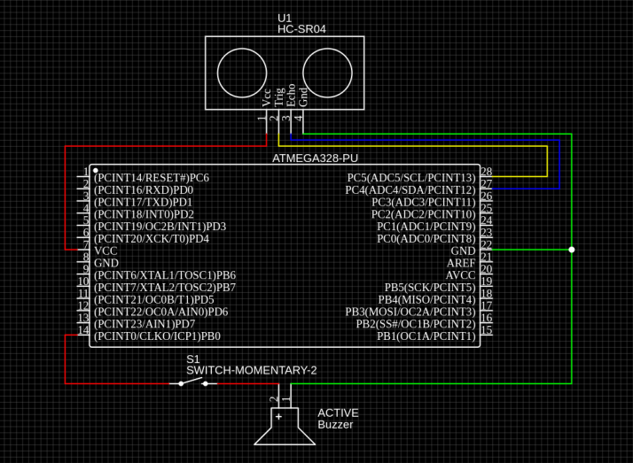
In the schematic above, we've simply switched the ESP32-WROVER-DEV for an ATmega328-PU and changed the wiring accordingly. On the HC-SR04 ultrasonic sensor, the VCC wires up to VCC pin 7 on the MCU, Trig wires to pin 28, Echo
wires to pin 27, and GND wires to the GND pin on 22, the MCU having 2 GND pins (8 & 22). The Active Buzzer's short leg is wired to GND on pin 22 and the longer leg is wired to pin 14. I've also placed a switch on the wire
path between the positive leg of the Active Buzzer and pin 14 of the MCU to give the user the option to enable or disable the beeping sound in settings they deem it fine to work without the beeping warning functionality
Adding an External Power Source & Voltage Regulator
I decided to add a 9V battery as an external power source, previously powered by a USB, and consequentially add a voltage regulator (LM7805) because our maximum voltage needed by any component is 5V, and we're inputting 9V with the battery. The regulator has an input range of 7-25V, an operating current (IQ) of 5mA, Internal Thermal Overload and Short circuit current limiting protection is available. Junction Temperature maximum 125 degrees celsius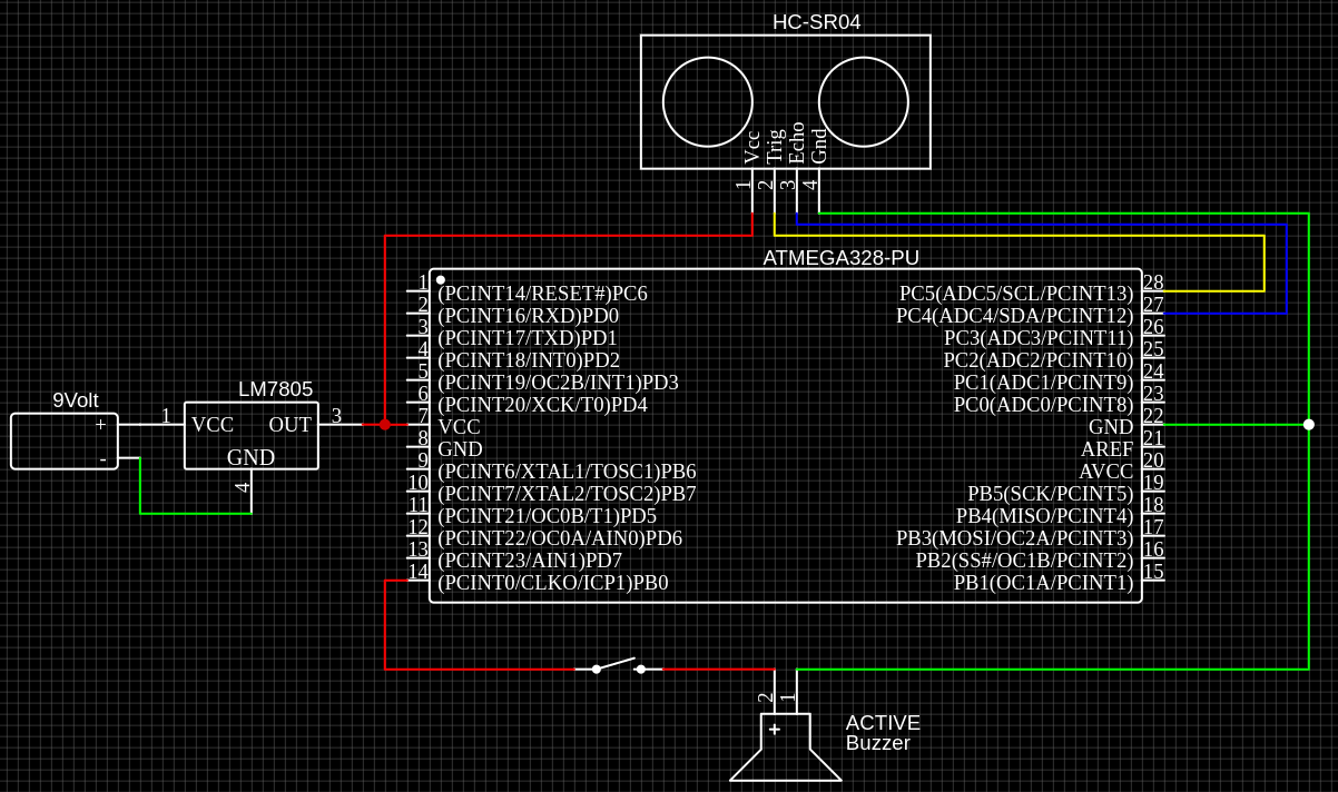
According to the schematic above, we've wired up the 9V battery's positive pin to the VCC pin on the regulator, and the negative pin on the battery to the GND pin on the regulator. Into the regulator goes 9V and comes out 5V through the OUT pin, which sends the electricity to the VCC pin. We only need to connect the battery's anode (-) to GND on the regulator unit.
So far, we've spoken about all except 1 important thing, amperage (current). In the context of your circuit, amperage (often used interchangeably with current) refers to the rate of electron flow at a specific point in the circuit. It essentially tells you how much electricity is flowing through a particular wire or component at any given time. In our circuit, the Battery supplies ≈ 1.3 amps, the HC-SR04 specifies that it needs 15 mA working current, 2 mA is "Quiescent", the active buzzer has a max rated current of ≤ 32 mA, and the MCU needs no more than 450 mA. According to the datasheet, the LM7805 outputs a constant amperage of 1. As we get close to that maximum output, the need for a heatsink becomes more inevitable.
Adding a Heatsink
As for adding a heatsink, I will have to run some practical tests and track the temperature of the voltage regulator with either a thermal camera or simply by feeling the temperature of the component every minute or so for about 30 minutes or more of continuous use. I am currently not able to conduct the test as I don't yet the heatsink kit that I've ordered.Code
below is the update code that uses our newly implemented ATmega328-PU:#define TRIG_PIN 28 // ATmega328 pin GPIO28 connected to Ultrasonic Sensor's TRIG pin #define ECHO_PIN 27 // ATmega328 pin GPIO27 connected to Ultrasonic Sensor's ECHO pin #define Buzzer 14 // ATmega328 pin GPIO14 connected to Active Buzzer's positive pin float duration_us, distance_cm; // Declare float variables void setup() { // begin serial port Serial.begin (9600); // configure the trigger pin to output mode pinMode(TRIG_PIN, OUTPUT); // configure the echo pin to input mode pinMode(ECHO_PIN, INPUT); pinMode(Buzzer, OUTPUT); } void loop() { // generate 10-microsecond pulse to TRIG pin digitalWrite(TRIG_PIN, HIGH); delayMicroseconds(10); digitalWrite(TRIG_PIN, LOW); // measure duration of pulse from ECHO pin duration_us = pulseIn(ECHO_PIN, HIGH); // calculate the distance distance_cm = 0.017 * duration_us; // print the value to Serial Monitor Serial.print("distance: "); Serial.print(distance_cm); Serial.println(" cm"); delay(500); if (distance_cm <= 5){ tone(Buzzer, 1000); delay(100); } else { noTone(Buzzer); delay(100); } }Please don't shy from sending suggestions or anything to the contacts listed in Whoami.
This website was made by me.
This page was made with only HTML & CSS. No JS
This page was made with only HTML & CSS. No JS