THE CYBER INFORMANT
Projects/BuzzCane: A cane for the visually impaired
2/3/2024
BuzzCane, my first hardware project to be showcased on my website, as well as the first project I have to do in my major studies as a computer & electric engineer. BuzzCane
is conscious of its surrounding, it uses an Ultrasonic Sensor to measure the distance between itself and solid surfaces it faces, if the distance is less than a specified value,
it sends wave pulses to an Active Buzzer to produce a buzzing (continuous humming) sound at a specified frequency for a set amount of time. All of these electrical components will be brought together by an
MCU (Microcontroller Unit). The MCU I've chosen is an
ESP32-Wrover-Dev that I purchased from Freenove.
As this is the first iteration of our project, I would like for it to be a proof of concept, a prototype, rather than a finished product. And so I will not prioritize using the most: power-efficient, cheap, and compact components. Nor will I worry much about making the breadboard wiring look as neat or implementing a
non USB-C power source. In the coming iterations of this project, I will focus more on using a smaller MCU with just the right amount of GPIO pins. And after that see if the ultrasonic sensor component could be reduced in size
and how would that affect the accuracy, range, and beam angle (angle of coverage) and how important are these changes in quality to our consumer demographic (visually impaired people).
Now that I have outlined the progression this project will follow, Let's get started by planning a prototype first before bringing it to the real world. for that I'll be using EasyEDA to make a schematic of the MCU & Electrical components.
Below is the simple initial setup and wiring of our MCU & ultrasonic sensor:
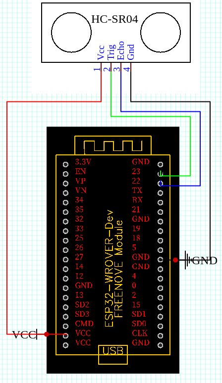
The image above shows a schematic of our ESP32-Wrover-Dev board being used to wire the HC-SR04 unit I've chosen as our proximity sensor. If you've never worked with MCUs before, or even worked a little, you're probably thinking now "How did he know to which pin of the MCU to wire each pin of the sensor?" To simplify it just enough so we can get the grasp of it and move on gracefully, MCUs have reserved pins that either input, output, or transfer specific protocols/types of data both ways. Specific pins such as 3.3V, GND, VCC, EN, CLK, etc... while other numbered pins are considered to be GPIO pins, pins that are uncommitted to any specific purpose or function, and so can be used to exchange all sorts of data we need. Please refer to ESP32 Pinout Reference for a detailed explanation on specific pin types and more info on GPIO pins.
In the schematic above, we wire the VCC on the HC-SR04 to the VCC pin on the MCU, supplying our sensor with 5 volts supply of power coming from our MCU connected to a computer (or any other compatible power source) with 5V of power.
We wire the GND pin in our sensor to a GND pin our MCU to complete the circuit and return the 5V supplied by VCC.
The Trig (trigger) pin on our sensor is wired up to any GPIO pin on our MCU. I chose GPIO 23. The Trigger pin works by sending signals to the Transmitting speaker, assigning it a state of either high or low. High and low are abstractions that represent the state of running voltage in a pin. High meaning running power/working/turned on, and low meaning no power runs through it / turned off. Depending on the state of the pin, it emits pulse waves in 40 KHz for a specified duration of time.
The Echo pin on our sensor is wired up to any GPIO pin our MCU. I chose GPIO 22. The Echo pin works by receiving the pulse waves that have a frequency of 40 KHz emitted by the T speaker. Similar to the Trig pin, the Echo pin also runs on high or low states, when the state is set to high it turns on the receiving speaker, and when the state is put to low, there is power running, it does not work to receive any wave pulses by the Transmitter.
HC-SR04 Internals
Above I've touched lightly and non-intrusively on how the ultrasonic sensor works. In this section we'll dive deeper into it and view charts and graphs that explain its quantitative and qualitative functions.According to the documentation linked above in the first paragraph, our HC-SR04 has a max range of 400 Cms and a close range of 2 Cms and an accuracy of ± 3 mm. It has a measuring angle of 15 degrees, operating voltage of 5 Volts DC, and an operating current of 115 mA.
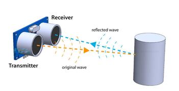
The ultrasonic sensor works by emitting 40KHz waves through the Transmitter (T) speaker that travel through the air, in case there is no solid surface for the waves to collide with and bounce back, they don't bounce back to the Receiving (R) speaker and get recorded into our screen as an existing object at X distance.
As explained above, the ultrasonic sensor generates 8 cycle ultrasonic bursts, traveling at the speed of sound, when the Trig pin is set on a high state for 10 µs (microseconds). After the bursts are sent, we then can set the Echo pin on high to start listening to any 40KHz waves that are reflecting back to it. In case there are reflected waves to be received, the Echo pin will automatically switch from a high state to a low state after 38ms. If a pulse is received by the R speaker, the Echo pin will transition to low state sooner than the default 38ms. And so, based on the time-span in which the Echo Pin was in a high state, we can measure the distance the sound waves had to travel from the T speaker, reflect off of a solid surface, and then travel the way back to the R speaker.
Please refer to this datasheet. for futher info, graphs, and to confirm what's above.
Calculating Distance
Using the numbers we receive above we can calculate the distance in Cms. We can use the simple formula of "Distance = Speed * Time". Now we're in a pretty good place because we know both the speed of sound (343 m/s) and the time in this context is for how long was the Echo pin in the HIGH state, and because the sound waves travel 2 ways, back and forth, and the equation above only accounts for whatever we're measuring only going 1 way, we will divide the result we get by 2 to only get the 1-way distance.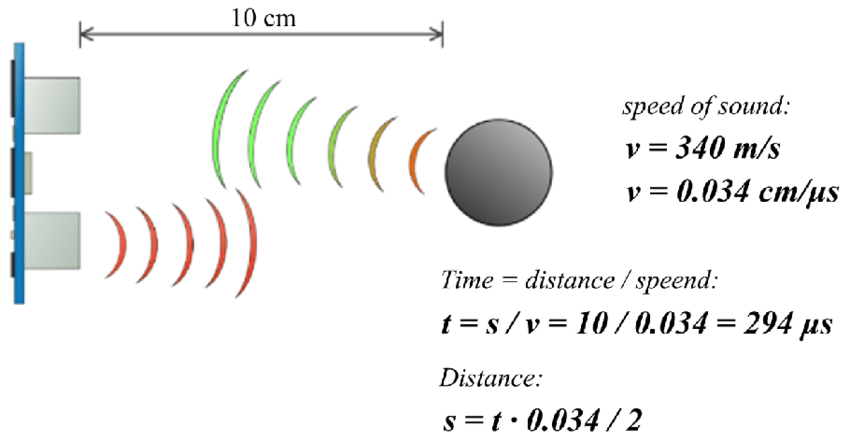
You might notice in the calculations above that we convert the speed of sound from meters/seconds to cm/μ, this is done because the duration measured by the ultrasonic sensor to receive the echo is in microseconds (μs). Therefore, to ensure consistency in units and to simplify the calculation, the speed of sound is converted from meters per second to centimeters per microsecond. This conversion allows for direct multiplication of the duration (in microseconds) with the speed of sound (in centimeters per microsecond) to obtain the distance in centimeters.
breadboard Prototyping
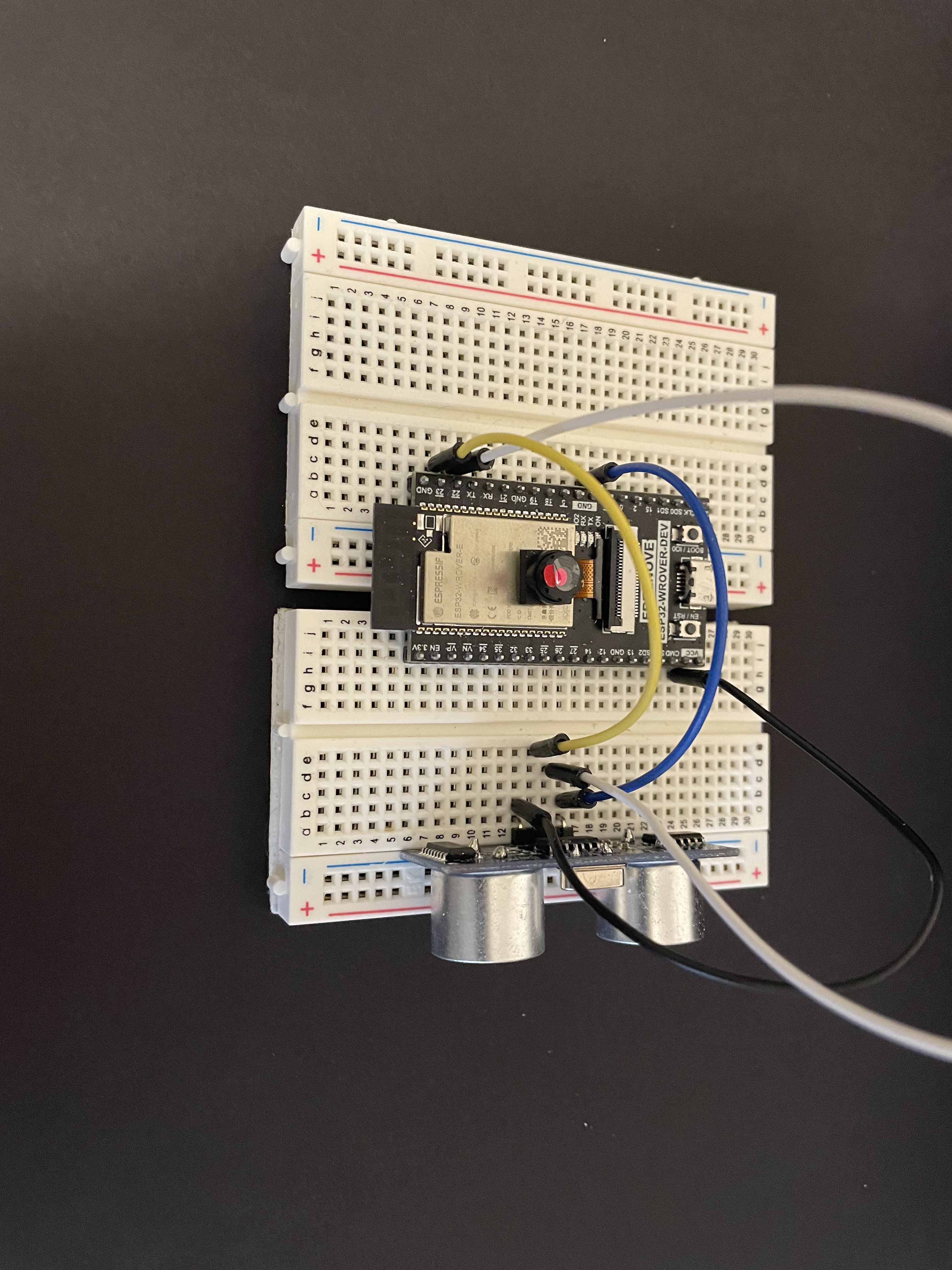
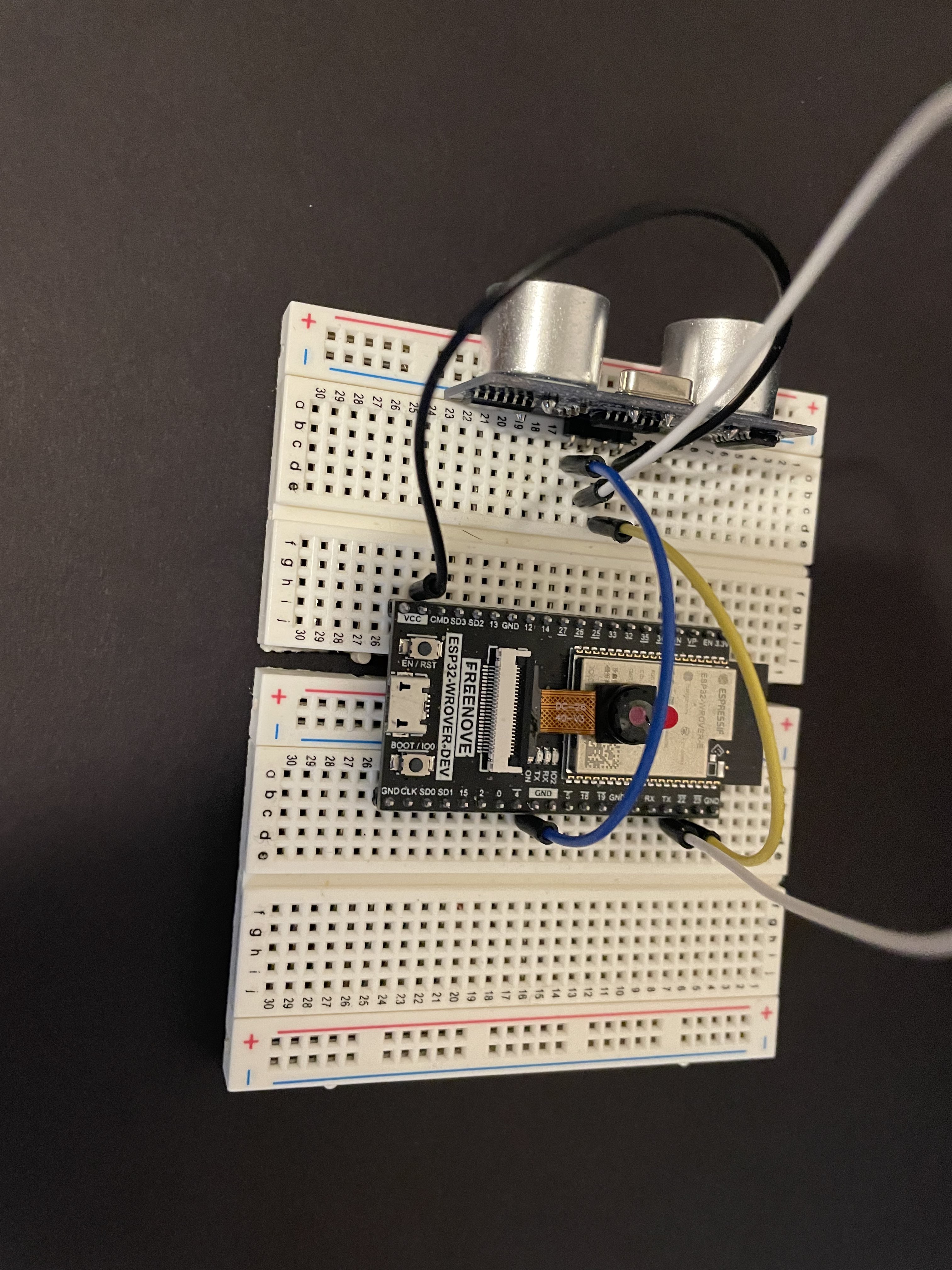
As in the 2 images above, I've installed my ESP32 MCU in between 2 little breadboards, I've installed the HC-SR04 supersonic sensor on the edge of the breadboard for optimum placement and for the HC-SR04 to have the best range. I've used Male-To-Male jumper wires to connect the pins of the HC-SR04 to the appropriate pins on the ESP32 MCU. Please refer back to the Schematic above for pin connections.
Adding an Active Buzzer
"How would the person using BuzzCane know when they're close to an object?" My answer to that is the use of an active buzzer that buzzes when the distance between the cane and a solid surface is ≤ 5 cms. Active buzzers are pretty simple to wire up and operate. They only require a source of power and need to connect to a pin to receive instructions (from an MCU). The active buzzer has an operating voltage of 4-8V DC (rated voltage 5-6V) and a rated amperage of < 30mA. It works by supplying an integrated oscillator circuit with power to then produce sound.Please refer to this datasheet for more info regarding active buzzers.
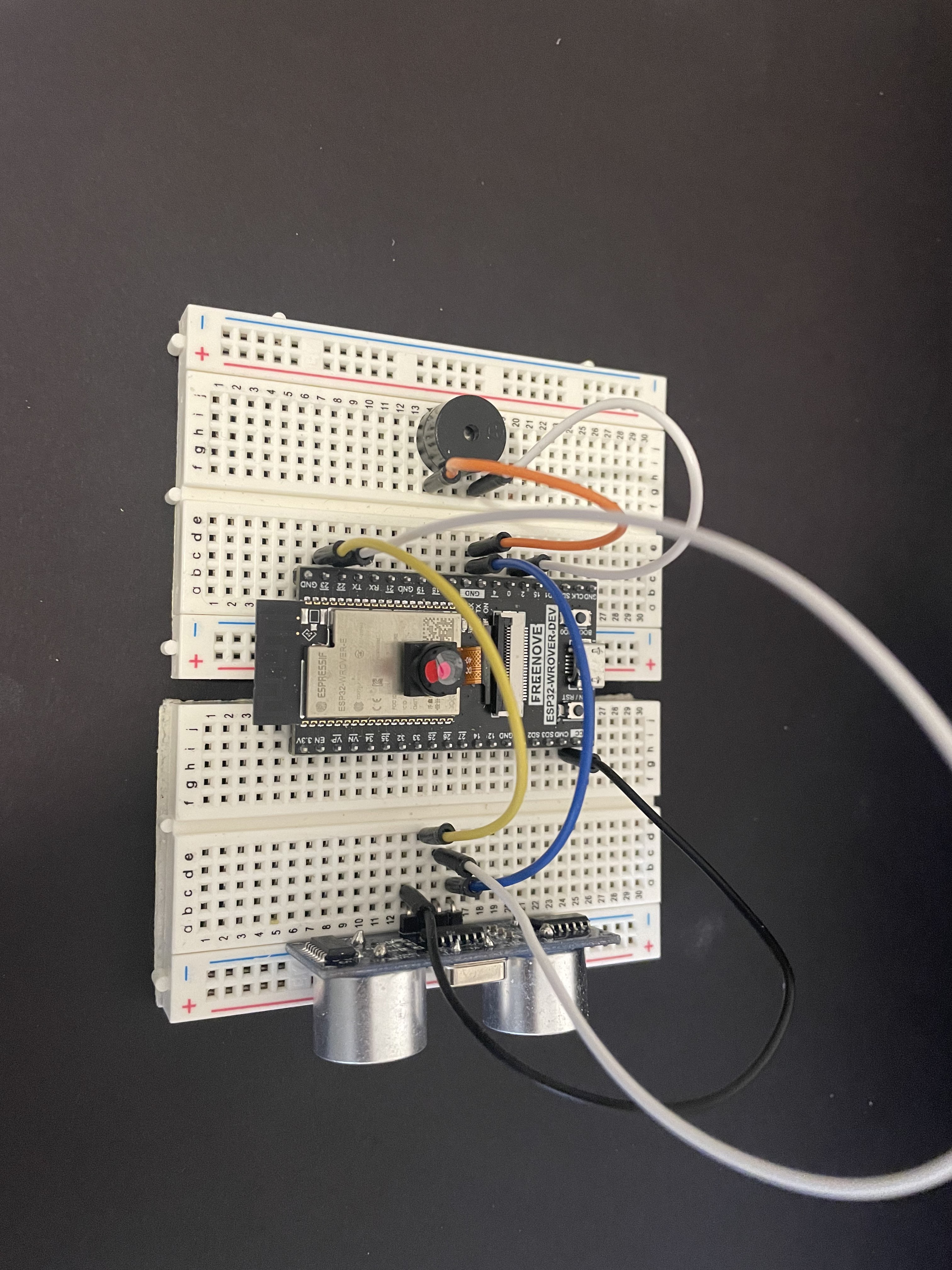
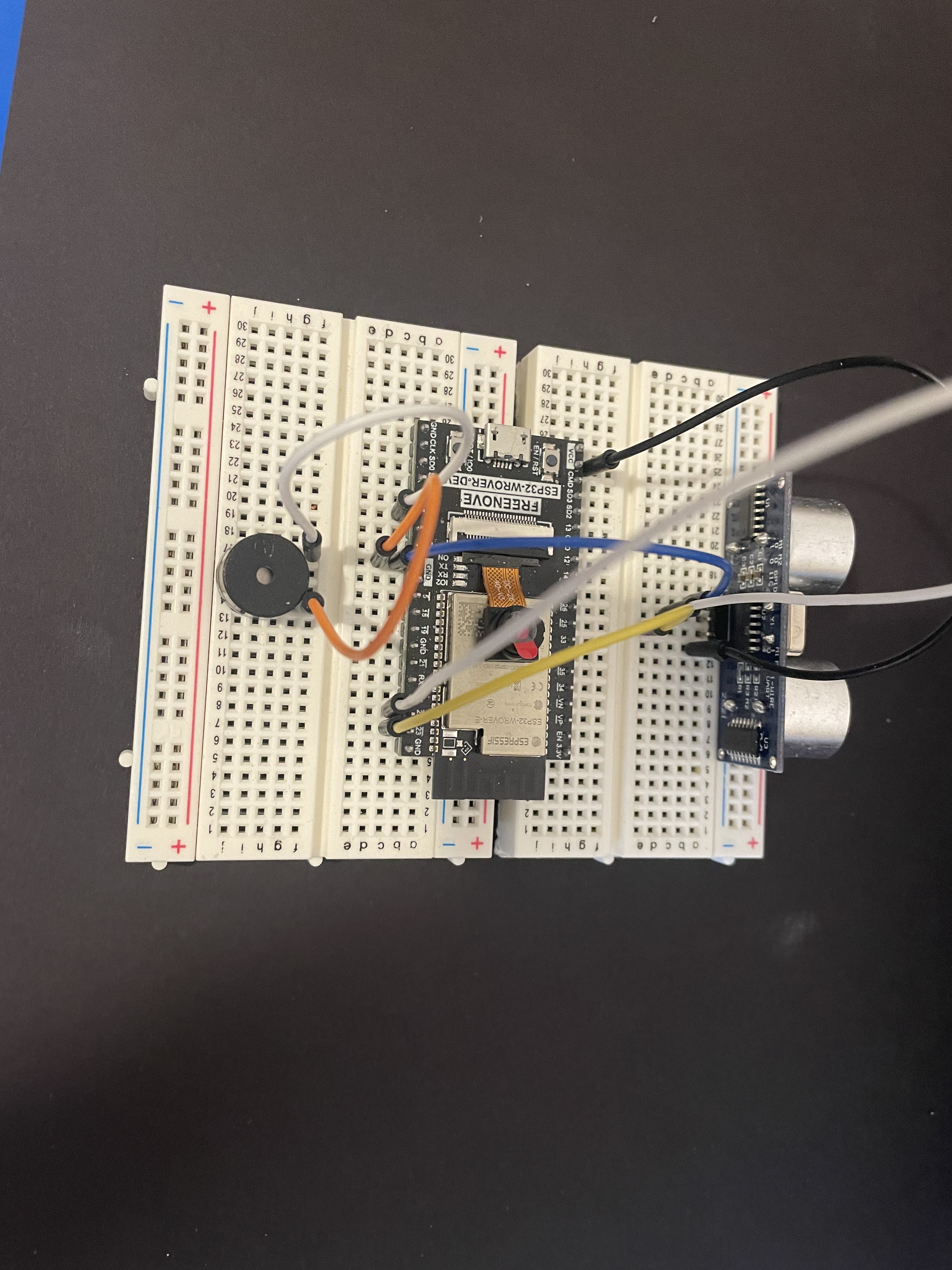
Below is what our schematic will look like once we add an active buzzer:
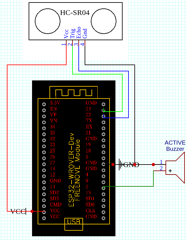
The negative pin is connected to GND and the positive pin is connected to any GPIO to receive instructions and power. Below is the breadboard prototype after adding our active buzzer:
Programming the MCU
Now that we have laid out the physical components and made connections to deliever power and data to components, it's time to program the logic our electronics will follow. Below is the complete code:#define TRIG_PIN 23 // ESP32 pin GPIO23 connected to Ultrasonic Sensor's TRIG pin #define ECHO_PIN 22 // ESP32 pin GPIO22 connected to Ultrasonic Sensor's ECHO pin #define Buzzer 2 // ESP32 pin GPIO2 connected to Active Buzzer's positive pin float duration_us, distance_cm; // Declare float variables void setup() { // begin serial port Serial.begin (9600); // configure the trigger pin to output mode pinMode(TRIG_PIN, OUTPUT); // configure the echo pin to input mode pinMode(ECHO_PIN, INPUT); pinMode(Buzzer, OUTPUT); } void loop() { // generate 10-microsecond pulse to TRIG pin digitalWrite(TRIG_PIN, HIGH); delayMicroseconds(10); digitalWrite(TRIG_PIN, LOW); // measure duration of pulse from ECHO pin duration_us = pulseIn(ECHO_PIN, HIGH); // calculate the distance distance_cm = 0.017 * duration_us; // print the value to Serial Monitor Serial.print("distance: "); Serial.print(distance_cm); Serial.println(" cm"); delay(500); if (distance_cm <= 5){ tone(Buzzer, 1000); delay(100); } else { noTone(Buzzer); delay(100); } }Below will be an explanation of the code segments above:
#define TRIG_PIN 23 // ESP32 pin GPIO23 connected to Ultrasonic Sensor's TRIG pin
#define ECHO_PIN 22 // ESP32 pin GPIO22 connected to Ultrasonic Sensor's ECHO pin
#define Buzzer 2 // ESP32 pin GPIO2 connected to Active Buzzer's positive pin
These lines define constants for the pin numbers connected to the ultrasonic sensor's TRIG pin, ECHO pin, and the active buzzer's positive pin.
float duration_us, distance_cm; // Declare float variablesThese lines declare global variables to store the duration of the pulse received by the ultrasonic sensor's ECHO pin (duration_us) and the calculated distance in centimeters (distance_cm).
void setup() {
    // begin serial port
    Serial.begin (9600);

    // configure the trigger pin to output mode
    pinMode(TRIG_PIN, OUTPUT);

    // configure the echo pin to input mode
    pinMode(ECHO_PIN, INPUT);

    pinMode(Buzzer, OUTPUT);
}
This function is the main program loop that runs repeatedly. It performs the following tasks: - Sends a 10-microsecond pulse to the ultrasonic sensor's TRIG pin to initiate a distance measurement. - Measures the duration of the pulse received by the ultrasonic sensor's ECHO pin. - Calculates the distance in centimeters using the formula provided (distance_cm = 0.017 * duration_us). - Prints the distance value to the Serial Monitor. - Checks the distance value and activates the buzzer if the distance is less than or equal to 5 cm. Otherwise, it turns off the buzzer. - Adds a delay of 500 milliseconds at the end of each loop iteration to control the sampling rate.
void loop() {
    // generate 10-microsecond pulse to TRIG pin
    digitalWrite(TRIG_PIN, HIGH);
    delayMicroseconds(10);
    digitalWrite(TRIG_PIN, LOW);

    // measure duration of pulse from ECHO pin
    duration_us = pulseIn(ECHO_PIN, HIGH);

    // calculate the distance
    distance_cm = 0.017 * duration_us;

    // print the value to Serial Monitor
    Serial.print("distance: ");
    Serial.print(distance_cm);
    Serial.println(" cm");

    delay(500);

    if (distance_cm <= 5){
        tone(Buzzer, 1000);
        delay(100);
    }

    else {
        noTone(Buzzer);
        delay(100);
    }
}
This function is the main program loop that runs repeatedly. It performs the following tasks: - Sends a 10-microsecond pulse to the ultrasonic sensor's TRIG pin to initiate a distance measurement. - Measures the duration of the pulse received by the ultrasonic sensor's ECHO pin. - Calculates the distance in centimeters using the formula provided (distance_cm = 0.017 * duration_us). - Prints the distance value to the Serial Monitor. - Checks the distance value and activates the buzzer if the distance is less than or equal to 5 cm. Otherwise, it turns off the buzzer. - Adds a delay of 500 milliseconds at the end of each loop iteration to control the sampling rate.
Demonstration
Please don't shy from sending suggestions or anything to the contacts listed in Whoami.
This website was made by me.
This page was made with only HTML & CSS. No JS
This page was made with only HTML & CSS. No JS